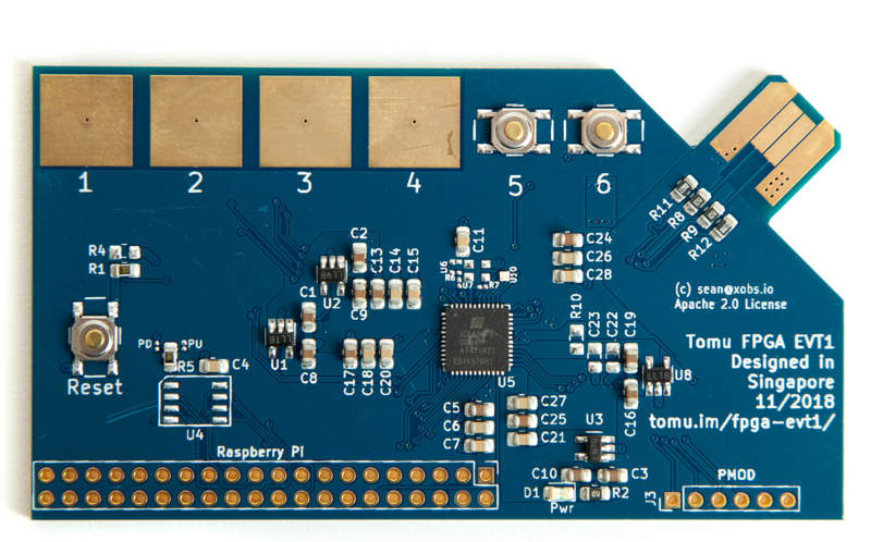


Fomu EVT2
This is a revision of the Fomu development PCB. It is easy to produce, and has lots of debug pins, but obviously doesn’t fit inside your USB port.
This improves on many of the design errors with EVT1. It also adds the following features:
- ESD protection (optional)
- More silkscreen indicators
- Alligator clip points for GND and power
- Easier to swap SPI from pullup to pulldown
Component Checklist
| Subsystem | Quick Test | In-Depth Test |
|---|---|---|
| 1.2V Reg | Pass | |
| 2.5V Reg | Pass | |
| 3.3V Reg | Pass | |
| VCCPLL Filter | Pass | |
| Xtal Oscillator | Pass | |
| SPI Flash | Pass (QPI) | FAIL (Identifier silk is swapped) |
| USB Pullup | ||
| USB Pad Polarity | ||
| RGB LED | Pass | |
| Captouch Pads | ||
| Capacitance | ||
| Reset Button | Pass | |
| User buttons | Pass |
Engineering Change Orders
Changes need to be made when producing EVT2. This is the list of changes to make:
ECO001: SPI PU/PD identification silk is swapped
*Description: SPI generally requires a pull on the chip select pin. The ICE40 changes its behavior depending on whether it’s a pullup or a pulldown. Fomu EVT has both options. The “PU/PD” indicator silk is correct, however R3 is labeled R13, and R13 is labeled R3.
Action: Swap R3 and R13 identifiers.
ECO002: Add a second PMOD header
Description: There are four touch pads, and four pins in a PMOD header. It would be nice to have an additional PMOD header for people who don’t want to use the touchpads.
Action: Add a second PMOD header near the captouch pads.
ECO003: Mask on USB connector scrapes easily
Description: Some USB ports have bits of rough metal that, over time, can scrape away at the solder mask and copper on the USB connector. This is purely a cosmetic issue, as the layer underneath is ground.
Action: Peel back the soldermask and copper layers on the underside of the USB connector, leaving bare FR4.
ECO004: I3C pins are split between PMOD and DAT4
Description: The ICE40 has one pair of I3C-capable pins. Right now those pins are split between PMOD_1 and DAT4, meaning this function isn’t very useful.
Action: Swap PMODa_1 and DAT4, so that the PMOD header will have a pair of I3C-compatible pins.
Raspberry Pi Usage
You can communicate with Fomu using fomu-flash.
Raspberry Pi GPIO pinouts
The BCM value here is the GPIO according to the Broadcom chip, and according to Linux. You can access these pins through /sys/class/gpio/gpio[BCM]/ or through gpio -g.
| BCM | Header | Signal |
|---|---|---|
| 17 | 11 | C_DONE |
| 27 | 13 | C_RESET |
| 24 | 18 | SPI_IO2/WP |
| 10 | 19 | SPI_MOSI |
| 9 | 21 | SPI_MISO |
| 25 | 22 | SPI_IO3/HOLD |
| 11 | 23 | SPI_CLK |
| 8 | 24 | SPI_CS |
Usage examples:
# Put the SPI flash in "HOLD" mode, so it ignores us.
gpio -g mode 25 out
gpio -g write 25 0
# Enable SPI flash "WP" mode
gpio -g mode 24 out
gpio -g write 24 1
# Put FPGA into reset
gpio -g mode 27 out
gpio -g write 27 0
# Monitor the C_DONE pin
gpio -g mode 17 in
gpio -g read 17 # Goes 1 when programming is done