


Fomu EVT1
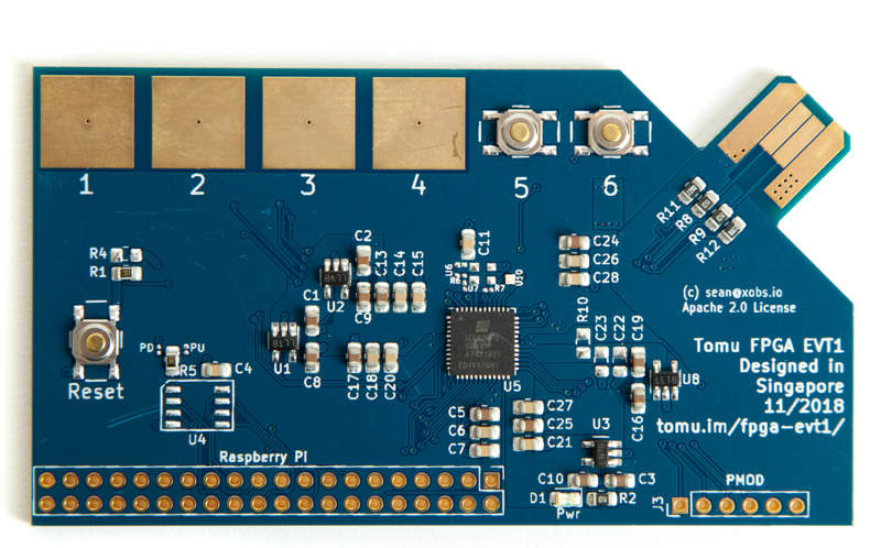
This is a development version of the Fomu PCB. It is easy to produce, and has lots of debug pins, but obviously doesn’t fit inside your USB port.
EVT1 was the first version of this board. It has many issues that were addressed in EVT2. If you want to produce a Fomu EVT board, we suggest you produce EVT2.
Component Checklist
| Subsystem | Quick Test | In-Depth Test |
|---|---|---|
| 1.2V Reg | Pass | |
| 2.5V Reg | Pass | |
| 3.3V Reg | Pass | |
| VCCPLL Reg | Pass | FAIL (ICE40 doesn’t like regulator here) |
| Xtal Oscillator | FAIL (Wrong footprint) | |
| SPI Flash | FAIL (Wrong footprint) | |
| USB Pullup | Pass | |
| USB Pad Polarity | Pass | |
| Captouch Pads | ||
| Capacitance | ||
| Reset Button | Pass | |
| User buttons | Pass | Partially pressing on the button gives a partial response. Why is that? |
Engineering Change Orders
Changes need to be made when producing EVT2. This is the list of changes to make:
ECO001: XTAL pin 1 is not NC
Description: The first pin of most XTALs needs to be floating (NC). This is in contrast to the MEMS oscillator which requires pin 1 be connected to pin 4.
Action: Modify the schematic so that pin 1 of the crystal oscillator is NC.
ECO002: SPI flash footprint is incorrectly sized
Description: The footprint for the SPI flash is sized according to the lead lengths, but is not wide enough. As a result, this part cannot be assembled.
Action: Increase the width of the pads in the footprint.
ECO003: USB footprint is slightly too narrow
Description: The USB footprint is slightly too narrow. As a result, it slides back and forth in the USB slot.
Action: Widen up the USB pad by 0.1mm
ECO004: USB board edge has too much clearance
Description: Because of the clearance on the edge of the PCB, it can rock back and forth. This, in combination with ECO003, means the PCB does not sit firmly in a USB slot.
Action: Extend the edge of the PCB towards the USB slot by 0.2mm.
ECO005: XTAL footprint is backwards
Description: The XTAL footprint has pin 1 in the upper-right-corner. However, the picture in the datasheet is mirrored, so pin 1 should actually be in the lower-left corner with numbering proceeding anti-clockwise (as opposed to the picture, which has pin 1 in the upper-right corner with numbering proceeding clockwise).
Action: Fix the footprint and redo wiring.
ECO006: VCCPLL regulator is in thermal overload
Description: The VCCPLL regulator was added to reduce the number of large capacitors, and to hedge against volatile capacitor prices. This is a 1.2V regulator, which should have a very clean output. Unfortunately, the ESD network of the ICE40 expects a simple filter network, and due to voltage rise times the ESD network falsely detects an event and shorts VCCPLL to GND. This causes VCCPLL to burn 200 mA as waste heat.
Action: Depopulate VCCPLL regulator and populate filter network instead.
Raspberry Pi Usage
You can communicate with Fomu using fomu-flash.
Raspberry Pi GPIO pinouts
The BCM value here is the GPIO according to the Broadcom chip, and according to Linux. You can access these pins through /sys/class/gpio/gpio[BCM]/ or through gpio -g.
| BCM | Header | Signal |
|---|---|---|
| 17 | 11 | C_DONE |
| 27 | 13 | C_RESET |
| 24 | 18 | SPI_IO2/WP |
| 10 | 19 | SPI_MOSI |
| 9 | 21 | SPI_MISO |
| 25 | 22 | SPI_IO3/HOLD |
| 11 | 23 | SPI_CLK |
| 8 | 24 | SPI_CS |
Usage examples:
# Put the SPI flash in "HOLD" mode, so it ignores us.
gpio -g mode 25 out
gpio -g write 25 0
# Enable SPI flash "WP" mode
gpio -g mode 24 out
gpio -g write 24 1
# Put FPGA into reset
gpio -g mode 27 out
gpio -g write 27 0
# Monitor the C_DONE pin
gpio -g mode 17 in
gpio -g read 17 # Goes 1 when programming is done